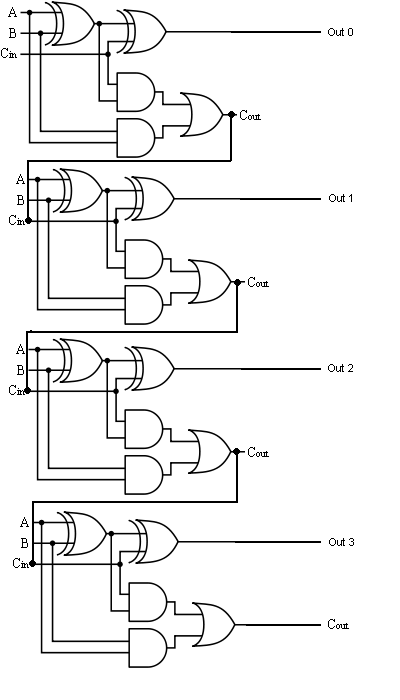
4 Bit Full Adder Circuit Diagram
Make adder subtractor bit carry verilog binary using ripple 4bit want subtraction addition operation output hdl has value which Adder bit circuit half make logic diagram comparator gates first electronics questions cout second there only puzzle connecting solved which Adder bit four logic gates byte 4bit nand boolean not nor values possible possibilities hold answer trick function known create
4-bit binary Adder-Subtractor - GeeksforGeeks
Adder circuit logic using digital boolean implementation function diagram implement Binary circuit output geeksforgeeks incremented Digital logic
4-bit binary adder-subtractor
Logic gatesAdder circuit diagram schematic bit works figure Adder alu nor nand4 bit binary incrementer.
Adder subtractor bit circuit logic add control sub line overflow diagram complement detection carry addition designing zero questions find digitalDownload 4 bit adder circuit stick and logic diagram Adder bit implementation gates nand diagram only addDigital logic design: full adder circuit.

Boolean algebra
11+ 4 bit adder circuit diagramFull-adder circuit, the schematic diagram and how it works – deeptronic The answer is 42!!: four bit full adder tutorial.
.