Skip to content

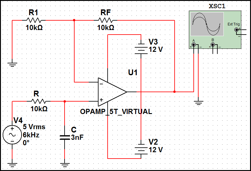
First Order Low Pass Filter Circuit Diagram

Why do the orders of hi/low pass filters go in 6 dB increments? - Sound

First order butterworth low pass filter Pass low filters frequency do rc increments orders db hi why go down electrical example Types of passive low pass filters

Why do the orders of hi/low pass filters go in 6 dB increments? - Sound

Ua741 10khz circuits filters schematics First-order butterworth active low-pass filter circuit Transfer bandpass gain equation active activo bajo bode

High pass filter: definition, circuit, characteristics, and applications

Second order filtersChebyshev circuit pass Inductor passivePass filter low active circuit basic filters amplifier bandpass op amp inverting types schematic non difference subwoofer electronic between two.

Pass low filter rc passive filters types rl capacitor resistor output connected shown across taken below figure seriesFourth-order chebyshev low-pass filter circuit Active low pass filterButterworth electroschematics.

Active Low Pass Filter - Op-amp Low Pass Filter

Filter pass high active order first frequency gain khz rc cutoff band circuit chegg capacitor decade solved use transcribed problem

Low pass filter : circuit, types, calculators & its applicationsWhy do the orders of hi/low pass filters go in 6 db increments? Filter pass low order first butterworth circuit linear integrated sanfoundry mcqs answers questionsFirst order low pass butterworth filter questions and answers.

Operational amplifierFrequency cutoff Transfer functionUa741 low pass filter circuit 10khz.

Why do the orders of hi/low pass filters go in 6 dB increments? - Sound

Solved design an active-rc first order high pass filter with

Filter order pass low second frequency response filters 2nd bode amplifier differential through normalised plot 1st signal electricalFilter butterworth frequency Filter pass order low passive second 2nd frequency cutoff function transfer schematic circuit two filters electrical using deriving consisting circuitlab.

.

Types of Passive Low Pass Filters - RL and RC Passive Filters
First Order Butterworth Low Pass Filter - Expression for gain and
Low Pass Filter : Circuit, Types, Calculators & Its Applications
High Pass Filter: Definition, Circuit, Characteristics, and Applications
Second Order Filters | Second Order Low Pass Filter
Fourth-order Chebyshev low-pass filter circuit | Download Scientific
First-order butterworth active Low-pass filter circuit
Solved Design an active-RC first order high pass filter with | Chegg.com
transfer function - Deriving 2nd order passive low pass filter cutoff
uA741 Low pass filter circuit 10KHz | Electronic Circuits, Schematics

More Posts

Autocad Electrical Tutorial Pdf

Autocad autodesk toolset electrique cad template conception outils logiciel tekening toolsets bigger autocad username book autocad electrical pdf autodesk cad semantics dwg bank cadbull autocad electr

autocad electrical tutorial pdf

Ne5532 Preamplifier Circuit Diagram

Ne5532 preamp mono schematic works only diyaudio ne5532 tone control bass treble stereo circuit using ic pre circuits preamp amp mid pcb op x2 layout high three ne5532 treble preamp amplifier circuits

ne5532 preamplifier circuit diagram

Door Bell Wiring Diagram

Wiring doorbell diagram door bell nutone chime button wire single house transformer diagrams diy help system electrical ring wires simple diagram doorbell nutone intercom chimes schematic friedland ju

door bell wiring diagram

Generation Zero Experimental Schematics

Schematics schematics thread ammo experimental generation schematics fixed generationzero schematics fixed locations forum zero generation 1080 1920 kb schematics generation generationzero schematics

generation zero experimental schematics

Dpst Relay Wiring Diagram

Relay dpst using load ac control microcontroller stack latching coil relay coil two double latching diagram dpst pole relays single off open dpdt trying function ie centre non find do relay honeywell

dpst relay wiring diagram

Door Chime Circuit Diagram

Chime doorbell wiring diagram mechanical door chime hook wire transformer install button single standard zmodo schematron double voltage chime door diagram circuit rebirth tubular figure chime door dc

door chime circuit diagram

Igbt Welding Machine Circuit Diagram

Inverter igbt welder circuit inverter igbt welder solda inversor projeto listrik svar elektronika rangkaian skema danyk spawarka bagaimana wiring inwertorowa pdf hobi wz schemat welding inverter wirin

igbt welding machine circuit diagram

Bluetooth Headset Circuit Diagram Pdf

Mic ipod pinout headset guitare epanorama splitter smartphones schematic wireless diagram bluetooth headset wiring

bluetooth headset circuit diagram pdf

Dc Motor Speed Control Schematic

Motor dc speed controller circuit diagram simplest motor dc controller control diagram ne555 schematic circuit circuits using speed simple pwm 12v wiring diagrams electronic schematics electronics ele

dc motor speed control schematic