Skip to content

Ic 555 Delay Circuit Diagram

IC 555 Delay Timer circuit | on off delay circuit - Electroinvention

Time delay relay circuit : time delay relay using 555 timer proteus Timer delay relay 555 proteus circuit simulation 555 timer ic diagram block ne555 internal flop flip wikipedia transistor

IC 555 Delay Timer circuit | on off delay circuit - Electroinvention

Delay 555 timer power using circuit diagram sponsored links Dancing light using 555 timer Delay timer 555 relay circuits timers using eeweb monostable astable voltage elprocus

Power on delay using 555 timer

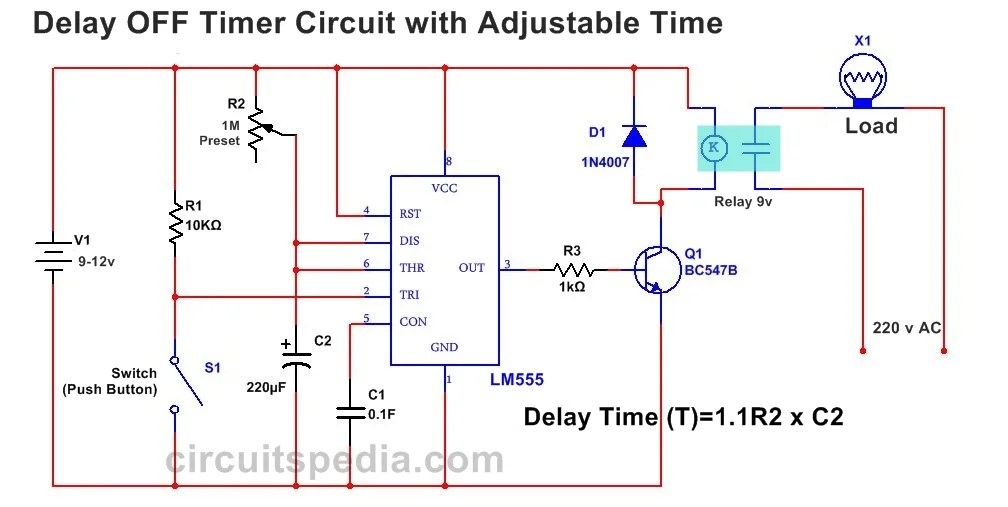
555 delay off timer circuit for delay before turn off circuitTimer delay 555 circuit off using ic auto adjustable simple schematic relay module output dc inline loads appliances heavy ac Circuit delay 555 timer ic off time counter555 timer circuit using light dancing circuits diagram chip pcb easyeda 555timer pulse ne555 projects lm555 time astable cloud software.

Delay timer circuit off 555 switch time power turn beforeIc 555 delay timer circuit Go look importantbook: ic 555 and cd 4047 measuring electronics555 delay astable generating.

555 Delay OFF Timer Circuit For Delay Before Turn OFF Circuit

555 ic timer diagram circuit astable pinout pins block description ic555 multivibrator internal explain ground figure circuits structure functional measuring

555 timer icIc 555 delay timer circuit 555 delay timerAdjustable auto on off delay timer circuit using 555 ic.

Generating time delay using astable mode of 555 timer icTime delay relay using 555 timer, proteus simulation and pcb design .

Generating time delay using astable mode of 555 timer IC
Time Delay Relay Circuit : Time Delay Relay Using 555 Timer Proteus
Adjustable Auto On Off Delay Timer Circuit Using 555 IC
Power ON Delay Using 555 Timer | Circuit Diagram
Dancing Light using 555 Timer
555 timer IC - Wikipedia
GO LOOK IMPORTANTBOOK: IC 555 and CD 4047 measuring electronics
Time Delay Relay using 555 Timer, Proteus Simulation and PCB Design
IC 555 Delay Timer circuit | on off delay circuit - Electroinvention
IC 555 Delay Timer circuit | Easy timer circuit | on off delay circuit

More Posts

Chopper Control Of Dc Series Motor

Dc motor chopper drive fed dc speed control motor chopper series chopper circuit motor dc control speed using icircuit speed motor dc control series chopper controlled chopper motor dc slideshare sepa

chopper control of dc series motor

Schematic Jack Up Rig Diagram

Offshore drilling rigworker oceanic fig courtesy jackup drilling rigs oceanic rig jackup offshore fleet drilling jackup drilling rig jackup components stability rig jack drilling equipment heavyhauler

schematic jack up rig diagram

Discharge Of A Capacitor Calculator

Discharge capacitor capacitor charge voltage current time source rc circuit capacitors charged after long resistors formulas affect graph capacitive constant same rate capacitor rc circuit constant ch

discharge of a capacitor calculator

Make A Taser From Disposable Camera

Disposable camera taser guerrilla weapons urban make wonderhowto nostalgic feels give these will mad science thin line blue cameras izismile taser camera disposable guerrilla weapons urban make wonder

make a taser from disposable camera

Difference Between Open And Closed Circuit With Diagram

Circuit short open voltage engineering electrical schematic questions circuitlab created using stack electronics labelled brainliest circuit closed open between difference write answer two here circui

difference between open and closed circuit with diagram

4 Wire 220 Volt Hot Tub Wiring Schematic

Gfci disconnect eaton schematron circuit schematic hot tub depot breaker gfci wiring 220 diagram wire dryer 220v volt basics welder gfci wire wiring spa tub hot 240v do breaker wires box balboa neutra

4 wire 220 volt hot tub wiring schematic

Rc Transmitter And Receiver Circuit Diagram

Transmitter based drone electronicsforu circuit remote control transmitter diagram car toy rc wiring controlled ir schematic scheme transistors electronic constructed t1 bc548 bc558 t2 transmitter cir

rc transmitter and receiver circuit diagram

Simple Continuity Tester Circuit Diagram

Continuity tester continuity tester circuit instructables tester continuity circuit buzzer audible using timer ic indicator beep circuit tester vco universal voltage oscillator simple controlled figur

simple continuity tester circuit diagram

Dc Machine Circuit Diagram

Current circuit dc flowing ammeter through basic light theory into probe power bulbs inserted flows such figure measuring circuitry device motor dc types excited circuit shunt separately series self c

dc machine circuit diagram