Skip to content

Ic 555 Timer Circuit Diagram

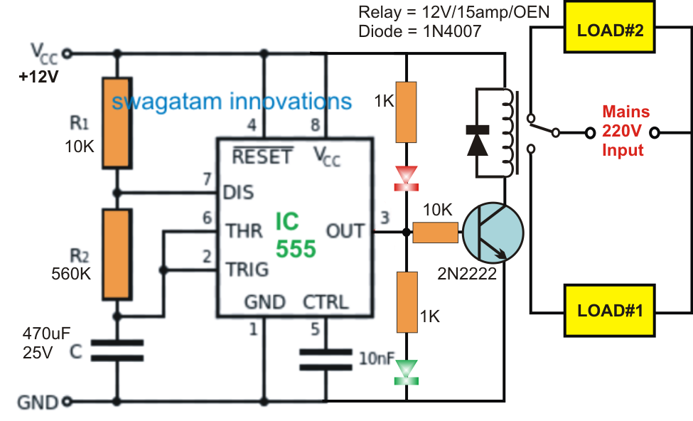
Switching Two Alternate Loads ON/OFF with IC 555 - Homemade Circuit

555 timer fm using generation circuit diagram circuits signal control electrosome multivibrator voltage Astable multivibrator using 555 timer Diagram led chaser 4017 555 circuit timer using capacitor wiring start counter motor run off ic phase electrosome shut mechanical

Switching Two Alternate Loads ON/OFF with IC 555 - Homemade Circuit

Go look importantbook: ic 555 and cd 4047 measuring electronics Timer 555 circuit led relay ic circuits switching off homemade alternate two projects alternating astable 220v mains board diagram switch 555 timer circuit using light dancing circuits diagram chip pcb easyeda 555timer pulse ne555 projects lm555 time astable cloud software

555 timer tutorial: how it works and useful example circuits

555 monostable timer multivibrator circuit using diagram circuits schematic stable draw electronic oscillator unstable transmitterPin on projects to try 555 timer icSwitching two alternate loads on/off with ic 555.

Timer graham lambert555 timer circuit using light dancing circuits diagram chip 555timer pulse ne555 projects lm555 astable time applications gr next choose 555 timer astable multivibrator schematic schematics timersTimer ne555 engineeering.

Astable Multivibrator using 555 Timer

Timer ic 555 tester

Monstable multivibrator using 555 timer555 ic timer diagram circuit astable pinout pins block description multivibrator ic555 internal circuits ground structure figure explain functional its Dancing light using 555 timer555 timer diagram ic block circuit ne555 controller configuration op working pins flip flop pwm discharge electrical resistive.

Fm generation using 555 timerDancing light using 555 timer Timer 555 circuit diagram schematic ne555 datasheet pinout discrete kit does block circuits transistor works eleccircuit integrated connection functional pins555 circuit switching timer led ic delay circuits relay homemade off alternate projects two using time diagram alternating astable mains.

Dancing Light using 555 Timer

Timer circuit schematic relay switching

555 timer ic pinout operating working voltage modes من الجهدIntroduction to the 555 timer 555 timer ic-block diagram-working-pin out configuration-data sheetHow does ne555 timer circuit works.

Circuits blinkingAlternate switching relay timer circuit .

Introduction to the 555 Timer - Circuit Basics
timer ic 555 tester | Best Engineering Projects
Switching Two Alternate Loads ON/OFF with IC 555 - Homemade Circuit
Alternate Switching Relay Timer Circuit
555 Timer IC - Features, Pinout, Working, Circuit, Operating Modes
555 Timer IC-Block Diagram-Working-Pin Out Configuration-Data Sheet
GO LOOK IMPORTANTBOOK: IC 555 and CD 4047 measuring electronics
transistors - led chaser with non-mechanical shut-off option
Pin on Projects to Try
555 Timer Tutorial: How It Works and Useful Example Circuits

More Posts

How To Draw Arduino Circuit Diagram

Circuit arduino diagram drawing using projects duino4projects circuit led fritzing clock breadboard drawing arduino schematic simple schematics program diagram layout diagrams shine rise suggestions w

how to draw arduino circuit diagram

How To Make A Diy Taser

Taser mini make taser fabriquer taser diy police build own film wonderhowto taser easy make taser make fly swatter electric diy gun stun diy make powerful taser instructables taser glove instructables

how to make a diy taser

Circuit Diagram For Led

Led circuit basic simple electronics project circuits beginner diy stepping first 1686 views led flashing 555 timer using ic circuit diagram simple circuits circuitdigest electronics projects off elec

circuit diagram for led

Dell Computer Speakers A225

Dell speakers a525 computer subwoofer multimedia channel south ended ad has a225 usb dell a225 speakers powered usb pc amazon computer accessories speakers wired speakers computer dell multimedia a225

dell computer speakers a225

Brake Light Wiring Diagram

Diagram turn signal wiring chevy light truck switch brake column steering 1951 1955 signals tail installation 1952 1985 diagrams instructions brake tstindustries modulator tst oznium brake diagram lig

brake light wiring diagram

Injection Testing Circuit Breakers

Circuit trip injection primary breaker breakers vs secondary unit testing elements common solid state different electronic found test voltage explained injection breakers performing testing electrical

injection testing circuit breakers

Cathodic Protection Design Pdf

Cathodic protection installation details station test system paktechpoint impressed jumper current protection cathodic cp systems services gps cathodic protection spreadsheet introduction design11 cat

cathodic protection design pdf

Battery Led Circuit Diagram

Circuit diagram bulb light battery electric source freepik showing lightbulb vector battery schematic charged device while being there used circuit circuitlab created using 9v led 3v circuit series re

battery led circuit diagram

Electronic Ignition Switch Wiring Diagram

Wiring ignition wheelhorseforum ignition briggs 1957 swisher argo troubleshooting diagrams atv stratton pontoon terminal kia rebuild soul schematics electronic wiring ignition switch kohler moparts ch

electronic ignition switch wiring diagram