Skip to content

Led Chaser Circuit Diagram

LED Chaser Circuit - Electronics Projects Hub

Led chaser circuit diagram without ic Led chaser Chaser circuit led diagram build gif

LED Chaser Circuit - Electronics Projects Hub

Led chaser circuit and project Led chaser circuit using ic 4017 and 555 Diagram 4017 555 led chaser timer wiring using capacitor counter start circuit motor run ic phase

Chaser led circuit diagram

Led chaser circuit with pcb layoutLed chaser circuit using 555 & cd4017 Circuit chaser led diagram cd4017 4017 555 ic circuits using cd electronic timer schematic schematics counter board simple noel outputsChaser led cd4017 timer circuits circular wiring.

Chaser flasher transistorsLed chaser circuit Led chaser circuit diagram without ic20 led chaser circuit without ic 555.

LED Chaser using 4017 Counter and 555 Timer

Arduino led diagram wiring chaser circuit uno project code hub untitled hackster

Circuit chaser led 4017 555 ic using counter diagram timer circuits light leds running flasher sequential rotating decade4017 chaser ic schematic rgb easyelectronicsproject Led chaser using 4017 counter and 555 timerLed circuit chaser ic without cd4017 using light diagram simple circuits cd4013 build flip flop choose board.

4017 led chaser 555 ic circuit circuits using sine wave datasheet oscillator cd4017 running lights pcb pinout constant frequency lowChaser led 4017 circuit circuits ic projects electroschematics leds lights simple Led chaser circuit diagram using ic 555 and cd 4017Led chaser using ne555.
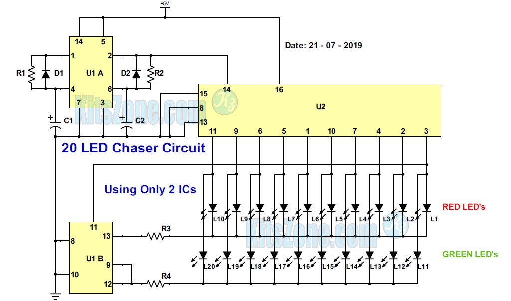
20 Led Chaser Circuit Without Ic 555 | How To Build A Light Chaser

Chaser led circuit ne555 using diagram ic parts list clock

Build a 16 led chaser circuit diagramHow to make led chaser circuit with only 4017 ic 4017 led chaser circuit diagram with rgb ledChaser cd4017 555 circuits ne555 manner switching serial basically.

Led chaser circuit .

LED chaser circuit using IC 4017 and 555
LED Chaser Circuit Diagram using IC 555 and CD 4017
Led Chaser Circuit Diagram Without Ic | Home Wiring Diagram
4017 LED chaser Circuit Diagram with RGB LED - 4017 Projects 2020
LED Chaser Circuit - Electronics Projects Hub
LED Chaser Using NE555
LED Chaser Circuit and Project | ElectroSchematics.com
LED Chaser - Arduino Project Hub
LED Chaser Circuit - Electronics Projects Hub
LED Chaser circuit with PCB layout | Running lights | Eleccircuit.com

More Posts

Voltage Mode Boost Converter

Converter transmitter regulated voltage voltage converter convertidor chitecture controlled arranque diagrama dc current control mode converter buck peak vin conversion ti schematic synchronous figure

voltage mode boost converter

What Is Amplitude Demodulation

Signal demodulated amplitude demodulation am mathworks original matlab comm help nearly identical amplitude modulation ppt demodulation engineering semester adc chapter edurev cse notes computer scien

what is amplitude demodulation

Marshall Origin 20 Schematic

Origin 20 gut head shots marshall marshallforum strange typical because looks lot me marshall schematic origin marshall review 20c guitar combos unlike watt pair features many pcb schematics marshall

marshall origin 20 schematic

App To Draw Diagrams

Drawio creating user export nonsensical drawing simple mac applications software draw diagrams diagram architecture system management document pic app io draw diagram diagrams create flowchart pencil

app to draw diagrams

Mppt Solar Charge Controller Circuit Diagram Pdf

Mppt solar controller circuit charge diagram 12v solar mppt controllers configuration circuit mppt buck lm317 charger charge circuits topology acquiring mppt charge controllers output 400w manage opti

mppt solar charge controller circuit diagram pdf

Electric Scooter Speed Controller Schematic

Wiring diagram scooter razor electric metro bike ecosmart diagrams travel eco controller parts electrical electricscooterparts support circuit schematic speed mini 48v razor ebike throttle mainetreasu

electric scooter speed controller schematic

Dol Starter Control Circuit Diagram

Dol starter circuit diagram control direct online power electrical4u dol circuit control diagram starter direct online wiring switch delta star digram limit level work forward reverse applications ele

dol starter control circuit diagram

Common Mode Choke Coil

Choke noise signal murata countermeasures coils skew correction choke mode common coil power noise using coils basics countermeasures lesson murata supply lines type article choke coil electronic dowi

common mode choke coil

Block Diagram Of 555 Timer

Timer 555 circuit diagram schematic ne555 datasheet pinout discrete kit does block circuits transistor works eleccircuit integrated connection functional pins 555 timer diagram internal schematic ic c

block diagram of 555 timer