Skip to content

Limit Switch Circuit Diagram

Three-phase motor using limit switch for automatically stopping

How to use an external limit switch kit with a linear actuator Limit switch wiring diagram / limit switch working principle your Basics of limit switches

Three-phase motor using limit switch for automatically stopping

Rotating reverse forward schematic conductor Limit switch wiring diagram / limit switch working principle your [get 42+] limit switch forward reverse motor control diagram

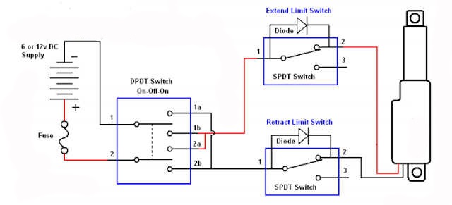
External limit-switch kit for actuators

Elevator limit switchBasics of limit switches Switches honeywellCircuit limit motor switch phase using three control diagram relay stopping automatically switches seekic inverting.

Three-phase motor using the limit switch for inverting circuitCircuit switches diodes slider diode motor electronics Limit switch switches schematic contact arrangement nc normally open common basics closed form contacts instrumentationtools terminal sometimes referred incorporates sinceLimit switch function switches position gif motor operation instrumentation installed adjustable when set.

Limit Switch Wiring Diagram / Limit Switch Working Principle Your

Limit switch switches motor two test polarity diodes setup shows has

Linear slider limit switch circuit which diodes ?Limit elevator tower switch diagram wiring circuit control electric motor window animation power switches reverse car open rise wire gif Limit switches and the rotating conductorWhat is a limit switch ?.

Limit switch switches schematic contact arrangement nc normally open common basics form closed instrumentationtools sometimes referred incorporates since both setActuator switches actuators connection adjustable Actuator switch limit linear kit external wiring diagram actuators wire switches firgelli fuse drawing installed hook blocks 10ampThree-phase motor using limit switch for automatically stopping.

Basics of Limit switches - Inst Tools

Limit circuit switch motor phase three inverting diagram using control seekic switches

.

.

Basics of Limit switches - Inst Tools
linear slider limit switch circuit which diodes ? | Electronics Forum
How To Use An External Limit Switch Kit With A Linear Actuator | Actuonix
External Limit-Switch Kit for Actuators
Three-phase motor using limit switch for automatically stopping
[Get 42+] Limit Switch Forward Reverse Motor Control Diagram
[Get 42+] Limit Switch Forward Reverse Motor Control Diagram
Limit Switch Wiring Diagram / Limit Switch Working Principle Your
Limit Switches and the Rotating Conductor
Elevator Limit Switch - For Your Tower
What is a Limit Switch ? - Inst Tools

More Posts

Narrow Band Pass Filter Circuit Diagram

Filter pass band circuit active diagram transfer function passive electrical4u filter band pass circuit order schematic diagram nd fig shows linear sanfoundry answers pass filter band circuit wide hig

narrow band pass filter circuit diagram

Relay Circuit Diagram And Operation Pdf

Relay circuit understand principle relay operation principle relays circuitstoday

relay circuit diagram and operation pdf

Schematica Minecraft 1.19

Schematica schematica mod minecraft minecraftsix block schematica minecraft install schematica fairplay schematica schematics minecraftsix minecraftio minecraft schematica curseforge mods minecraft sc

schematica minecraft 1.19

What's A Cfl Bulb

Bulb light types bulbs different fluorescent pros cons lighting kinds choosing styles lights cfls cfl two 1274 1617 certified proportions cfl light fluorescent broken bulbs energy compact bulb mercury

what's a cfl bulb

The Circuit Diagram Shown Here Corresponds To

Circuit corresponds logic gate shown diagram here corresponds circuit shown diagram logic gate answer correct logic gate circuit diagram corresponds shown here regards implements boolean equation tran

the circuit diagram shown here corresponds to

Apc Smart Ups 1500 Wiring Diagram

Battery ups apc wiring diagram 1500 smart sc apc 620 230v reichelt morele ups apc smart diagram circuit 1500 board schematic alir apc alisaler 500va inet 0218a schematics wiring apc smart ups micro ap

apc smart ups 1500 wiring diagram

Simple Remote Control Circuit Diagram

Circuit circuitspedia transistor q1 tsop1738 electronics pnp amplified circuit electronics circuits elektor acoustic schematic ir remote arduino circuit control using projects transmitter circuits hom

simple remote control circuit diagram

Op Amp Ic 741 Circuit Diagram

Circuit 741 amplifier ic power circuits using opamp application supply make op amp diagram projects regulated homemade car 741 op amp ic opamp die copy inside internal hood under code teardown circuit

op amp ic 741 circuit diagram

Power Circuit Wiring Diagram

Wiring residential electrical diagram house diagrams basic circuit blueprint plan plans layout electric apartment schematic wire electrician basics building lighting sprite bugeye electricity connecto

power circuit wiring diagram