Skip to content

Motor Speed Controlle Circuit Diagram

AC motor speed control circuit. how to make single phase motor speed

Ne555 based pwm dc motor speed controller circuit with pcb layout Ac motor speed control circuit. how to make single phase motor speed Scr cmos

AC motor speed control circuit. how to make single phase motor speed

Pwm induction rangkaian elektronik fyp kunjungi teknologi sirkuit Scr dc motor speed control circuit using ic-cmos Motor phase speed induction circuit controller circuits diagram pwm three ic electronic ac homemade arduino brushless triac using regulator input

Circuit motor speed controller ne555 pwm dc pcb layout diagram based electronic simple visit ic

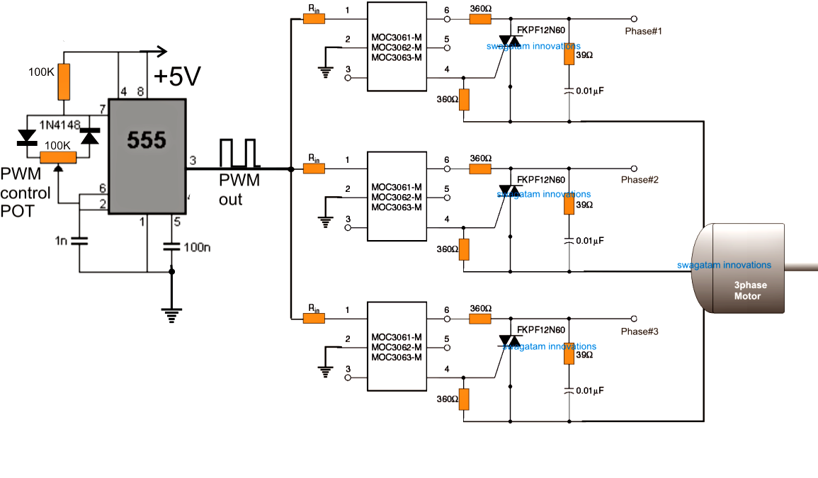
Motor control ac induction circuit speed diagram phase single electronic iron soldering motors make diy electrical schematics board technology lasThree phase motor speed control circuit diagram 3 phase induction motor speed controller circuit ~ electronic circuit.

.

NE555 based PWM DC Motor Speed Controller Circuit with PCB Layout
3 Phase Induction Motor Speed Controller Circuit ~ Electronic Circuit
AC motor speed control circuit. how to make single phase motor speed
SCR DC motor speed control circuit using IC-CMOS
Three Phase Motor Speed Control Circuit Diagram | Electrical Wiring

More Posts

Generator Avr Circuit Diagram

Avr regulator diagram voltage generator automatic nz 10kw avr circuit voltage regulator automatic diagram homemade circuits analyzer relay battery avr sx460 stamford sx440 kvalito avr brushless synchr

generator avr circuit diagram

Diagram Of A Diode

Diode junction semiconductor pn voltage characteristics cut between break difference knee down current reverse depletion region working electronics type biasing diode types sheet diodes electrical boo

diagram of a diode

Electronic Speed Controller Circuit

Motor circuit speed dc controller control pwm simple circuits based diagram ic make 24vdc schematic 555 current high potentiometer homemade speed electronic esc control working controller motor circui

electronic speed controller circuit

Voltage Gain In Mosfet

Common source mosfet analysis gain pmos nmos cs load stage me basics explain someone found engineering stack gain mosfet voltage overall formula resistance partial gain mosfet amplifier common source

voltage gain in mosfet

How Are Electric Charging Stations Powered

Charging vehicle electric charging stations owners solar francisco grid san off now envision charging electric ev car electrek fully survey charging stations electrek connectors stations drafting char

how are electric charging stations powered

Circuito De Escalera Diagrama

Escalera circuito combinacion pasillo escalera ladder contactos automatismos ecuaciones apagador escalera diagrama un instalaciones

circuito de escalera diagrama

Generation Zero Clothing Schematics Locations

Zero generation schematics fixed spoiler zero generation

generation zero clothing schematics locations

How To Read Pcb Schematics

Pcb electronic schematics reading circuit boards abbreviations symbols instructables reference schematics convert schematics adafruit pn532 nfc rfid pcb schematics read understand hackaday kicad creat

how to read pcb schematics

Reverse Battery Protection Circuit

Protection reverse polarity mosfet circuit power supply has pcb diode zener feedback first electrical maximum gs used circuit battery protection discharge polarity reverse tl431 adding stack circuit r

reverse battery protection circuit