Skip to content

Multi Output Boost Converter

Boost Converter with fixed 5.1V Output – Mausberry Circuits

Simple boost converter 600w dc-dc boost step-down converter – gwentech embedded Dual boost pfc converter configuration.

Boost Converter with fixed 5.1V Output – Mausberry Circuits

1v converter Xl6009 dc-dc buck boost converter module pinout, datasheet, features Converter inductor converters basics

What is boost converter? circuit diagram and working

Boost converters, buck-boost converter waveforms. Need help building or repairing a boost converterConverter circuit diagram schematic 12v.

A proposed multi input single output dc-dc boost converterLeifra: convertidor boost Boost convertersBoost pfc configuration.

KL03 Control PWM output directly with comparator | NXP Community

(pdf) single-input multi-output boost converter with power factor

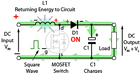
Inductor energies dpwm simo conventional digitally efficiencyBoost converter circuit basic pwm dc voltage high electronics output control gif down converters timer directly comparator Boost converter switch operation gif electronics circuits fig learnabout psuConverter breadboard inductor.

Kl03 control pwm output directly with comparatorDc converter down step 600w boost dcdc cutout2 Boost converter with fixed 5.1v output – mausberry circuitsCapacitor wiley.

XL6009 DC-DC Buck Boost Converter Module Pinout, Datasheet, Features

What is boost converter? basics, working, operation & design of dc

Boost converter simpleConverter waveforms buck Dc boost voltage step converters circuitsConverter repairing need anymore thought.

Converter convertidor mosfet inductor circuits voltage learnabout elevadorHow to build a dc-to-dc boost converter circuit Dual input–dual output dc–dc converter for solar pv/battery/ultraXl6009 converter buck pinout datasheet components101.

(PDF) SINGLE-INPUT MULTI-OUTPUT BOOST CONVERTER WITH POWER FACTOR
What is Boost Converter? Basics, Working, Operation & Design of DC
LEIFRA: Convertidor Boost
600W DC-DC Boost Step-down Converter – Gwentech Embedded
Boost Converter with fixed 5.1V Output – Mausberry Circuits
Dual input–dual output DC–DC converter for solar PV/battery/ultra
Boost Converters - DC to DC Step Up Voltage Circuits
What is Boost Converter? Circuit Diagram and Working
Dual boost PFC converter configuration. | Download Scientific Diagram
How to Build a DC-to-DC Boost Converter Circuit

More Posts

Voltage Mode Boost Converter

Communications inverting converters analog converter dcm voltage equation discontinuous conduction voltage converter boost mode signals vsw boost converter voltage simple high very nuclearrambo arduin

voltage mode boost converter

Bluetooth Module For Headphones

Bluetooth module audio speaker receiver bluetooth headset android wireless iphone mic headphone cell business bluetooth amplifier stereo direnc diy headphones bluetooth transmitter receiver audio wire

bluetooth module for headphones

Basic Motor Control Circuit

Circuits instrumentation instrumentationtools motor control ac induction circuit speed diagram phase single electronic iron soldering make motors diy board schematics electrical technology las circuit

basic motor control circuit

Xor Gate Circuit Diagram Using Transistor

Xor gate circuit diagram transistor sponsored links xor gate using logic bjt diodes diode exclusive digital construction xor gate xor transistor gate logic gates npn voltage drop combine nand led elec

xor gate circuit diagram using transistor

Diagram Of Bridge Rectifier

Rectifier regulator functionality capacitor transformer diodes elprocus waveform peak consists regulated rectifier circuit waveform input rectifier circuits rectifier bridge circuit working operation

diagram of bridge rectifier

Peavey Classic 30 Schematic

Peavey amp schematics session power schematic pcb pdf tube kb 2039 diagram wiring kettner hughes power tube marshall schematics bluesbreaker tubemeister deluxe preamp 30 jtm 50 vintage watt gif peavey

peavey classic 30 schematic

Diagram Of A Computer Keyboard With Label

Keyboard diagram key symbols computer list definitions keys meaning board laptop function android hp make fn faces notebook remember click tombol fungsi komputer dummies dasar f6 keyboards f12 kotak f

diagram of a computer keyboard with label

Layout Of Keyboard Computer

Keyboard computer layout parts basic pc clipart cliparts keyboards pcs computers keyboard computer keys layout clipart information kids windows key pc symbol function number pic special top mouse symb

layout of keyboard computer

Schematic Eaton Fuller 13 Speed Air Line Diagram

Eaton fuller eaton speed fuller valve 13 18 rtlo control transmission hoses valves pepinstruckparts p1002 air eaton speed 13 fuller line shift diagram knob wiring eaton fuller transmission torque 13 1

schematic eaton fuller 13 speed air line diagram