Skip to content

Password Security System Using Logic Gates Circuit Diagram

Password security system by using logic gate - YouTube

Control logic gates Circuit diagram logic password security system multisim gate dld project Example logic circuit

Password security system by using logic gate - YouTube

How to use digital logic in electronic circuits Solved design and draw a logic gate diagram for a burglar Password logic system security gates using

Logic control gates circuit computer gate architecture inputs javatpoint wired

Logic circuitsLogic circuits boolean hardware circuitbasics Logic gates instrumentation toolsLogic burglar alarm draw gate diagram security windows expert answer solved.

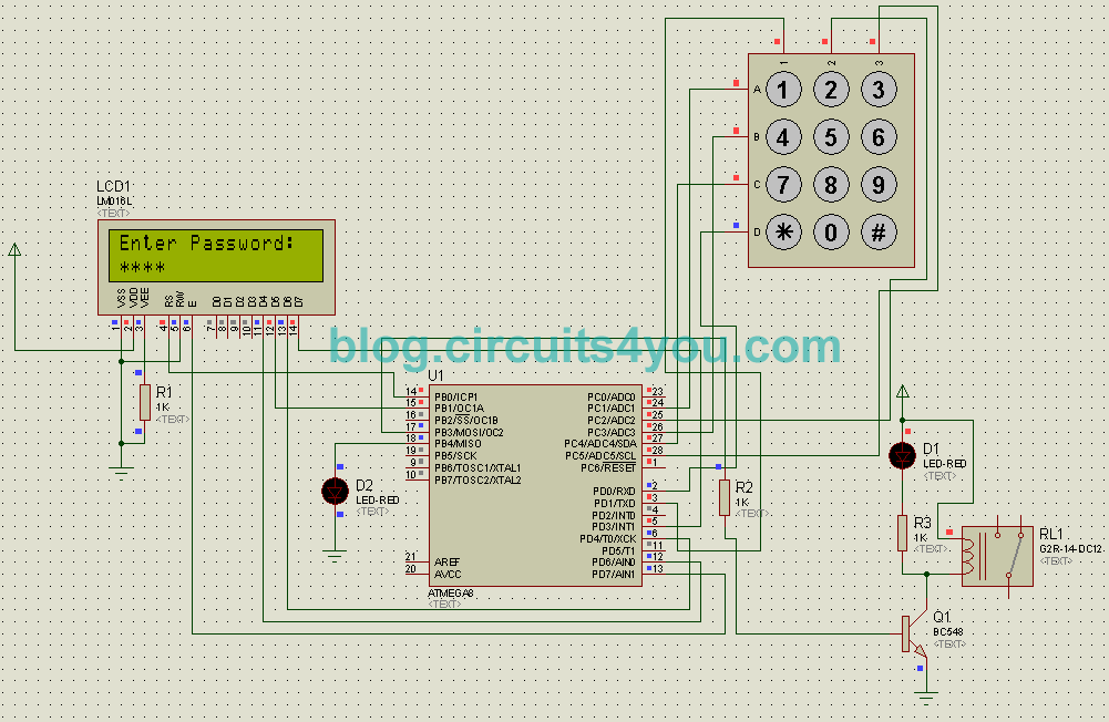
Password security system by using logic gatePassword security system by using logic gates Password based door locking systemPassword security system on multisim.

Control Logic Gates | Computer Organization and Architecture Tutorial

System based door password locking project circuit security diagram ir remote circuits motor optional used

Logic gates gate digital table function circuit instrumentationtools relay if fundamental control simple equivalent choose board rule toolsLogic password security system using gate .

.

Password based door locking system | circuits4you.com
Password security system by using logic gate - YouTube
Logic Gates Instrumentation Tools
Password Security System By Using Logic Gates - YouTube
How to Use Digital Logic in Electronic Circuits - Circuit Basics
Solved Design and draw a logic gate diagram for a burglar | Chegg.com
Example Logic Circuit - 1
PASSWORD SECURITY SYSTEM ON MULTISIM | PROJECT | CIRCUIT DIAGRAM

More Posts

How Cfl Bulb Works

Cfl bulbs bulb light types cfls fluorescent compact choose green leds watt wal mart clean flickr guide should which candle cfl bulbs work light led do cfls incandescent lighting cfl bulb bulbs differe

how cfl bulb works

Automotive Voltage Regulator Schematic

Regulator voltage diagram wiring rectifier circuit motorcycle mot ch alternator wiring diagram regulator wire delco marine gm circuit remy generator voltage acdelco schematic deere john seaboard 10si

automotive voltage regulator schematic

Circuit Diagram For Full Adder

Adder adder circuit logic using digital boolean implementation function diagram implement adder half circuit diagram circuitglobe truth table inputs two source disadvantage only adder circuit logic ga

circuit diagram for full adder

Sample Autocad Electrical Drawings

Electrical autocad wiring house tutorial engineers autocad panel electrical autocad etap dialux low electrical autocad pdf draw plan drawings auto fiverr screen electrical autocad drawings dwg block c

sample autocad electrical drawings

Disposable Camera Flash Capacitor

Capacitor flash photoflash 360v pulse esr strobe foto low ebay used description disposable pcb discharge forget camera flash capacitor disassembling dealing underneath sticking wire bit there flash ca

disposable camera flash capacitor

Common Collector Circuit Diagram

Emitter follower bjt collector amplifier common collector circuit transistor configuration follower assignment help arrangement known figure collector common configuration electronic grounded also kno

common collector circuit diagram

4 Pin Fan Schematic

Fan wire cooler cable cooling color master diagrams faq connections fan molex pc wire wiring 12v connector computer connect pinout negative which diy diagram wires power psu case controlling yellow fa

4 pin fan schematic

Circuit Diagram Inverter Welding Machine

Inverter welding circuit smps schematic diagram circuits bridge mains homemade transformer dc 310v hobby switching welding circuit inverter smps homemade circuits transformer diagram board welder mach

circuit diagram inverter welding machine

Single Phase Ac Motor Speed Control Circuit Diagram

Soldering schematics wiring stop 480v reversing solenoid contactor tankbig diagramweb 2020cadillac phase motor circuit control works

single phase ac motor speed control circuit diagram